Adding Test Machines to your farm
Introduction
Important
This section assumes you have a CI-tron instance up and running.
When designing a test system, it is important to keep in mind that test results need to be:
Stable: Re-executing the same test should yield the same result;
Reproducible: The test should be runnable on other machines with the same hardware, and yield the same result;
Introspectable in real time: Real time logs of operation massively increase the trust-worthiness of test results and thus the likeliness they won’t get ignored.
The stability and reproducibility requirements impact the choice of test machines, their configuration, and their mode of operation:
Fully power cycle the test machine between each test cycle: this helps reset the hardware and firmware;
Treat local storage as cache that can be flushed when testing fails, and use durable storage (NVME, SSDs) or go diskless;
Let the test control as much of the test environment as possible by ceding control of the test machine right after platform initialization, or as close to it as possible;
Use serial consoles: They are pretty universal, cheap, and provide easy to grep logs contrary to screen captures.
In order to fully power cycle machines, we need a way to remotely control its power delivery, this is the focus on the next section.
Step 1: Power delivery
Remote control of power is best achieved using a Power Delivery Unit (PDU). PDUs come in many form factors, operating voltages, ports count, and control protocols. Let’s have a quick overview:
Mains-switching PDUs
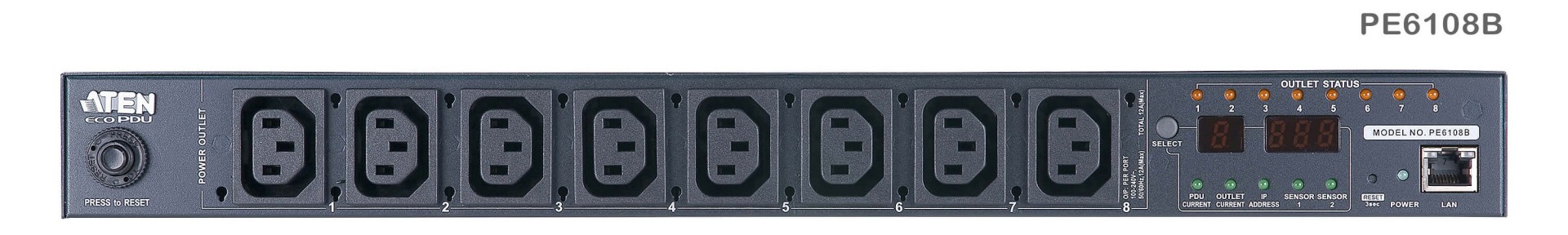
A rack-mounted power delivery unit.
The traditional solution for servers is to use rack-mounted power delivery units which are controlled using SNMP over ethernet. They are probably the most reliable, but also the priciest options. Make sure to check your local eBay rather than buying them new!
Pros |
Cons |
|---|---|
✅ Rock solid |
❌ Initial purchase cost |
✅ SNMP-based wired connectivity |
❌ Lack of per-port power monitoring |
✅ Industrial rating |
❌ Messy cabling |
Known-working PDUs:
APC Masterswitch (driver:
apc_masterswitch)Cyberpower (driver:
cyberpower_pdu41004orcyberpower_pdu15swhviec12atnet)Any other SNMP-based PDU, if you can find it in the Online MiB Browser (driver:
snmp)

A WiFi-controlled smart plug, with power monitoring
A popular alternative to rack-mounted PDUs are wireless Smart Plugs such as the Shelly Plug S, or any Tasmota-compatible plugs.
Pros |
Cons |
|---|---|
✅ Easy to source, and lower cost |
❌ Requires a compatible WiFi adapter |
✅ Easier wiring |
❌ Lower reliability due to WiFi |
✅ Per-port power monitoring |
Known-working PDUs:
Any WiFi Shelly device (driver:
shelly)Tasmota-compatible plugs (driver:
tasmota)
DC-switching PDUs
Power-over-Ethernet
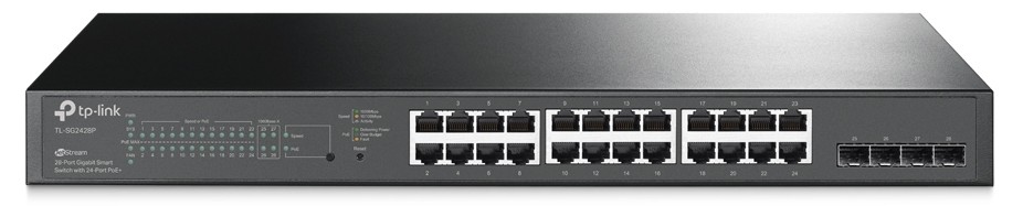
An SNMP-controlled managed Ethernet Switch with PoE
For low-power DUTs, such as single-board computers, a very attractive solution is to use Ethernet to provide both power and data. This makes cabling a breeze while staying relatively affordable.
Pros |
Cons |
|---|---|
✅ Easiest cabling |
❌ Best sourced second hand |
✅ Smallest footprint |
❌ Limited per-DUT power budget |
Known-working PDUs:
Linksys LGS326MP Smart Switch (driver:
snmp_poe)TP-Link Smart Switch with Power-Over-Ethernet (driver:
snmp_poe_tplink)Any other standard PoE switch (driver:
snmp_poe)
Relay boards
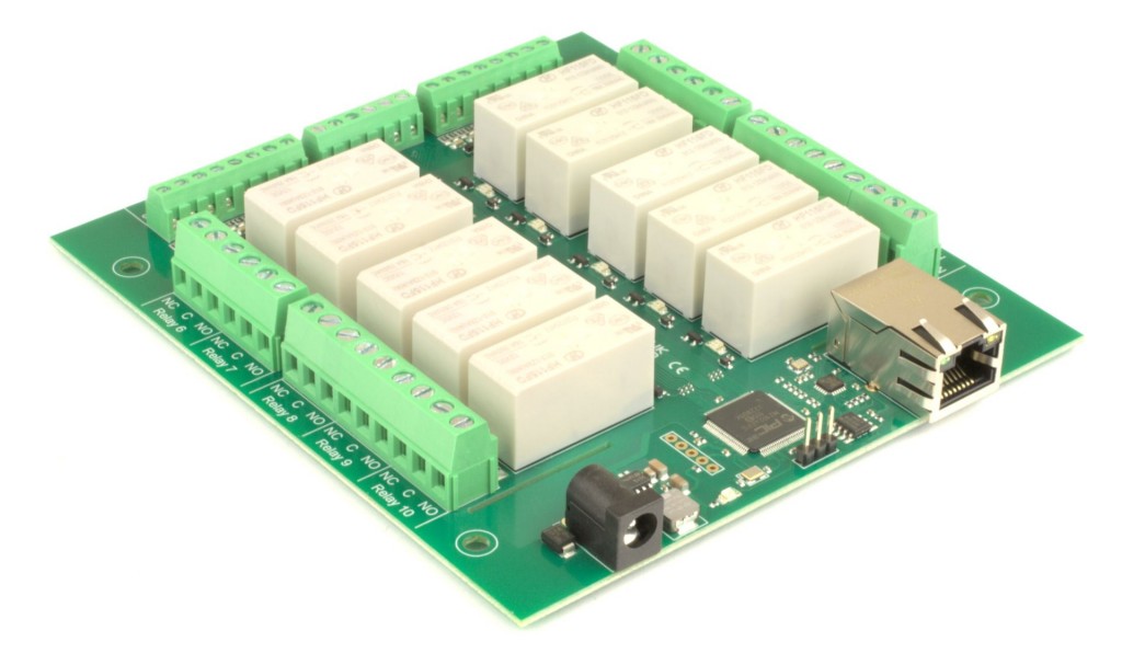
An Ethernet-controled relay board
Another alternative for DUTs that are powered using barrel jacks or screw terminals is to use a relay board.
Pros |
Cons |
|---|---|
✅ Cheap |
❌ Janky, requires strain relief |
Known-working PDUs:
Devantech Ltd network based relays (driver:
devantech)KernelChip network based relays (Laurent-2,5,112,128) (driver:
kernelchip)KMTronic UDP LAN Relay Controllers (UD2CR, UD4CR, UD8CR) (driver:
kmtronic-udp)
USB Hub with Per-Port Power Switching
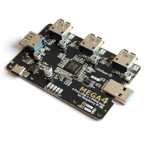
A USB Hub with Per-Port Power Switching
For devices that are primarily powered using USB, these hubs are the equivalent to Power-over-Ethernet switches. They however are difficult to find, and rarely have unique serial numbers which makes it difficult to operate when having more than one.
Pros |
Cons |
|---|---|
✅ Cheap |
❌ Hard to find hubs with unique serialno |
✅ Combines power and data |
❌ May require plugging one hub at a time |
Known-working PDUs:
Virtual Here USB Hub (driver:
usbhub). Caveat: Limited power available, may require a Y-cableUUGear Mega 4 (driver:
usbhub). Caveat: Requires plugging hubs one at a time for auto-discovery to succeed
Adding the PDU to your CI-tron instance
Now that you have your PDU in hand, you’ll need to get CI-tron to make use of it.
For simplicity and security reasons, CI-tron provides separate networks for
internet connectivity (public), DUTs (private), and management
infrastructure (mgmt). The specifics of adding your PDU to the right network
differ based on its connectivity:
Ethernet
By default, any Ethernet port that is not connected to the internet / providing
the default route is dynamically added to the private network.
You may move Ethernet adapters from the private to the mgmt network,
by setting the NET_MGMT_STATIC_ALLOC variable in /config/config.env to a
comma-separated list of their MAC addresses.
For example: NET_MGMT_STATIC_ALLOC=DE:AD:BE:EF:00:14,DE:AD:BE:EF:00:15
After a reboot, you should see in your dashboard that mgmt network would
have more network interfaces in it.
You may then plug your PDU to one of the network interface you’ve dedicated for
the mgmt network.
WiFi
By default, any WiFi adapter connected to your CI-tron gateway will become an
access point which is connected to the mgmt network.
The config file for the access point to control the AP name, channel, and more
is located at /config/network/hostapd-mgmt.conf.
Make sure to replace the default passphrase before connecting your PDU to it.
Making use of your PDU
Now that your PDU is “physically” connected to the CI-tron instance, you may already see it appear in the dashboard. This is because CI-tron supports auto-discovery of PDUs, provided that the following conditions are met:
The PDU is plugged on the
mgmtor theprivatenetworkThe PDU has a unique identifier (MAC address, or USB serial number)
No credentials are needed to access the PDU. For SNMP PDUs, enable SNMPv1 and use the
privatecommunity.
If your PDU was not auto-detected, you may want to check the executor’s logs
using journalctl -fu executor as you are power-cycling your PDU and follow
the recommendations there.
If you see no activity in the executor logs, check out the management network
leases in /config/network/mgmt.leases.
Warning
If you cannot find your PDU in the leases file, it is possible that the PDU is using a static IP by default rather than DHCP. Please fix that before making progress.
You may finally add your PDU to /config/mars_db.yaml:
pdus:                                           # List of all the power delivery units (MANUAL)
  APC:                                          # Name of the PDU
    driver: $driver                             # The [driver of your PDU](pdu/README.md)
    config:                                     # The configuration of the driver (driver-dependent)
      hostname: $ipaddr
Check out our PDU module for more details about the expected option for your driver.
If all went well, you should now see your PDU appear in the dashboard along with the state of every port:
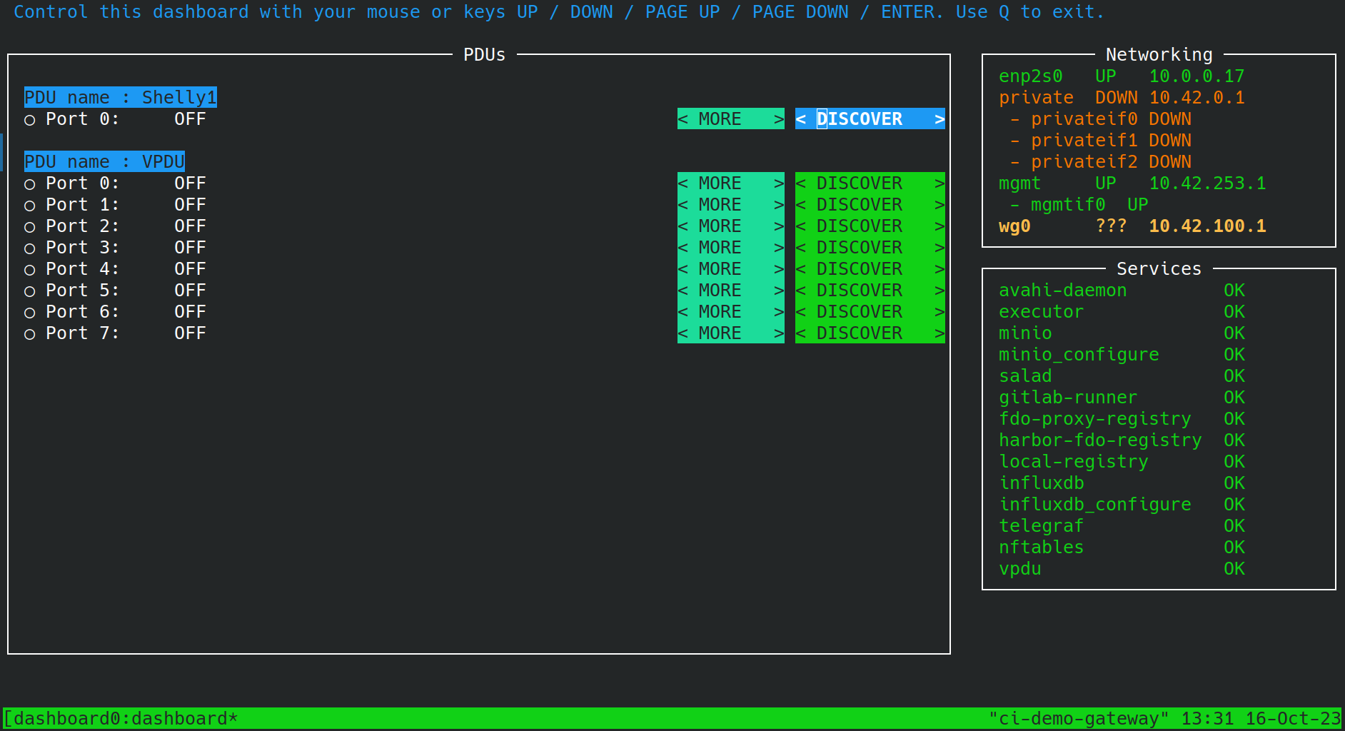
The state of the dashboard, after adding a Shelly Plug S PDU
Configuring your DUT to automatically boot up when powered
Some DUTs may not automatically boot when the power is applied. You may fix this
by enabling the Boot on AC Power option in your firmware:
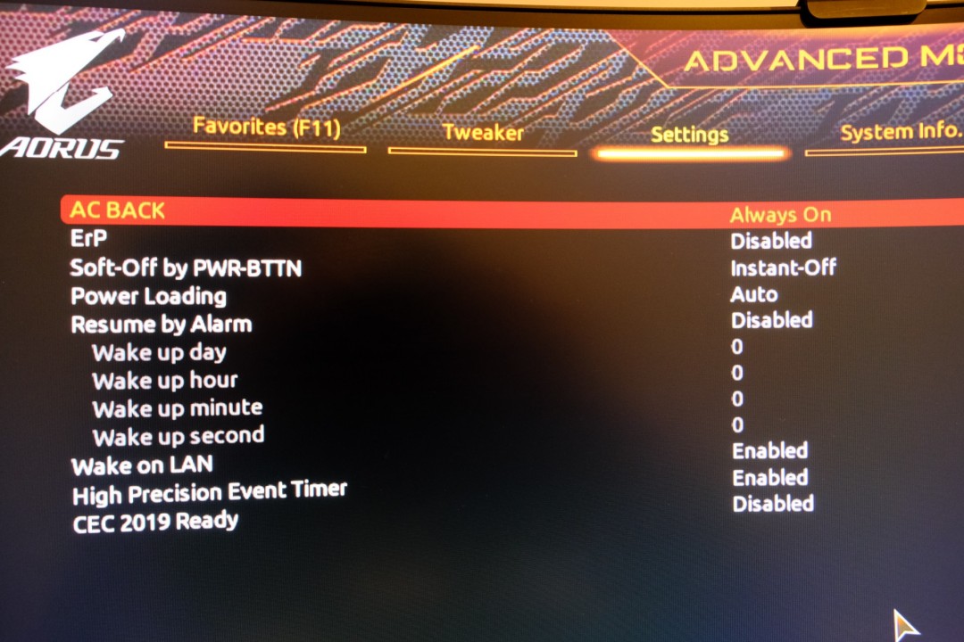
An AMD platform |
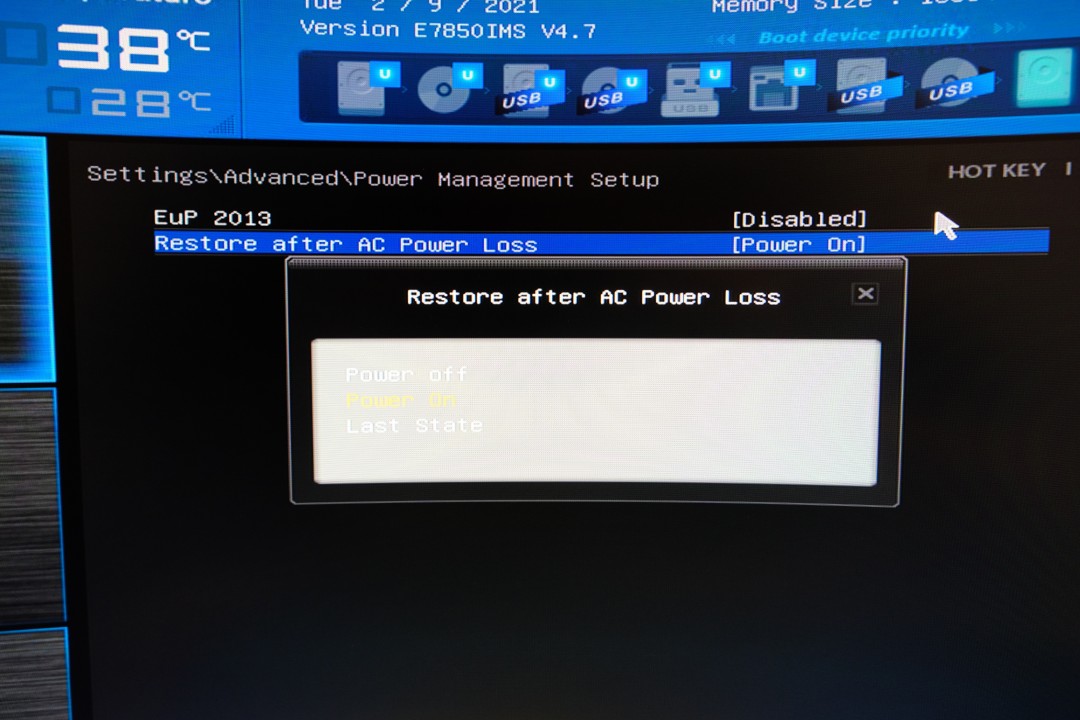
An Intel platform |
If you cannot find such setting, please take a look at our NoBootOnAC help.
Step 2: Configuring the firmware
CI-tron supports the following boot methods:
PXE Boot on x86_64, arm, and arm64 (TODO: riscv64)
U-Boot: There are two possibilities:
Using PXE Bootmeth
Using a custom boot command (see U-Boot Configuration Requirements)
Fastboot: ⚠ you will likely need to add explicit support for every device
Regardless of the boot method selected, CI-tron is expecting for DUTs to advertise themselves in a specific-enough fashion to select the correct boot artifacts: CPU architecture, file-transfer protocol (TFTP, HTTP), DTB filename, …
See also
Support for all the above boot methods is implemented in a YAML file: boots_db.yml.j2.
You may override this file by placing a copy in /config/boots_db.yml.j2,
unless you’ve modified the BOOTS_DB_USER_FILE parameter in the
Executor configuration.

Enable the onboard LAN controller |
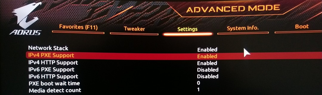
Enable the network stack support |
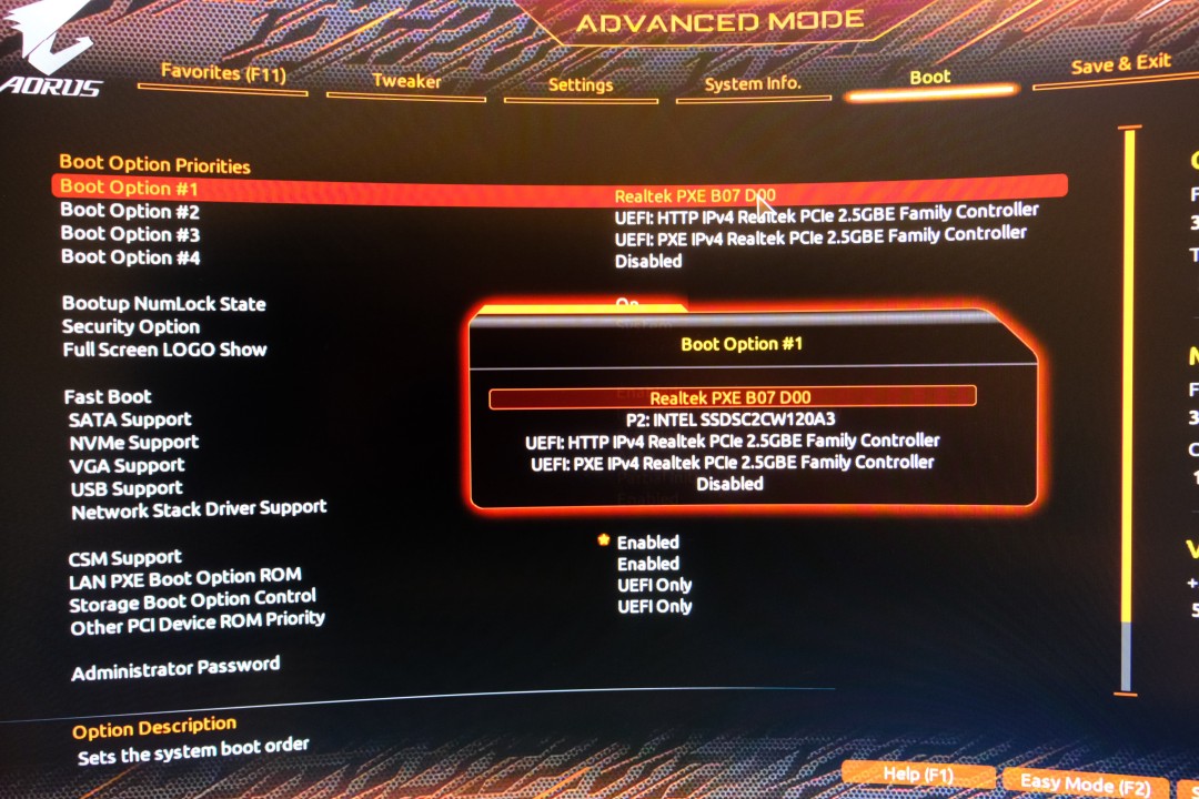
Prioritize PXE / netboot |

Enable the onboard LAN controller |
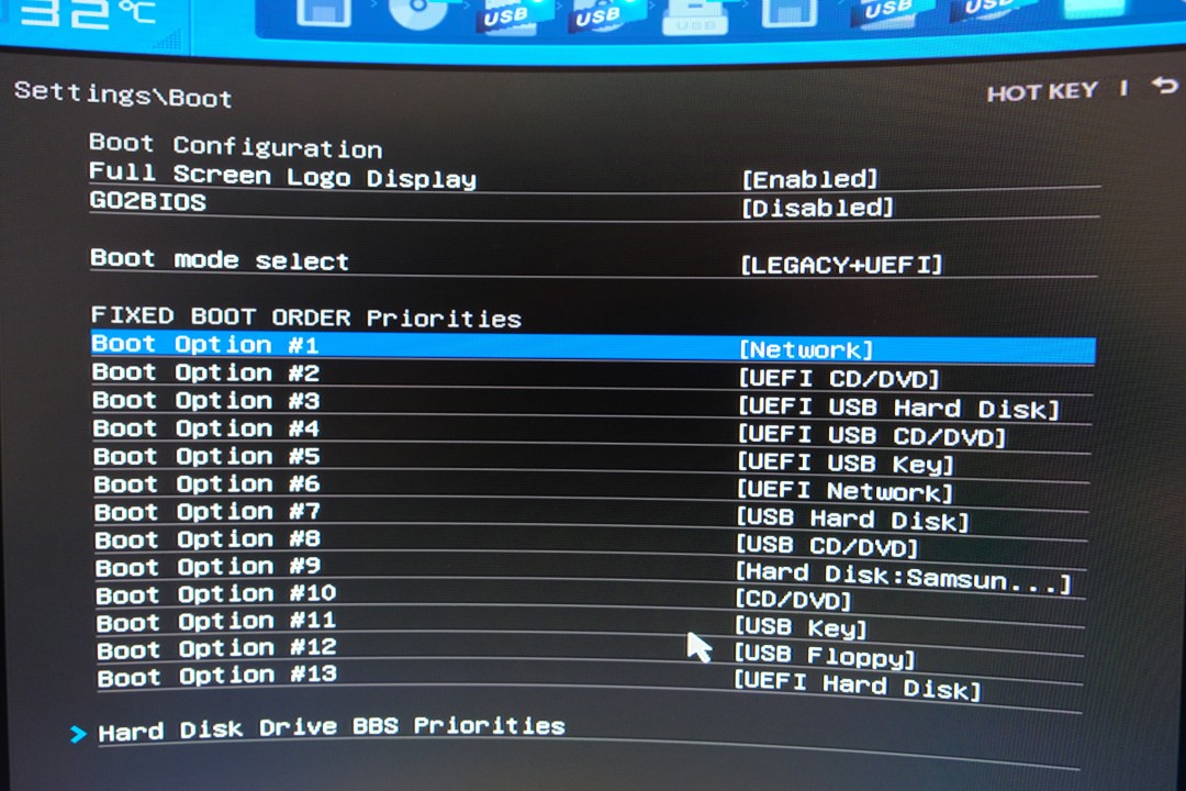
Prioritize PXE / netboot |
If your test machine’s firmware does not support any netbooting method, you may still flash a different bootloader on an SD-Card or a USB stick that would provide you with this functionality.
Popular choices are iPXE (TFTP or HTTP boot), or U-Boot (TFTP, HTTP, or fastboot).
U-Boot Configuration Requirements
When using U-Boot with a custom boot command, the following options in U-Boot’s .config file are required:
CONFIG_LEGACY_IMAGE_FORMAT=y- Required for loading legacy U-Boot image formats
Boot command setup
If your current U-Boot binary doesn’t currently advertise your test machine in a clear-enough fashion for CI-tron to be instructed how to boot it, you will need to modify the default boot command in order to specify for example, the fdt_file before issuing a DHCP request.
The recommended approach is to set CONFIG_BOOTCOMMAND at build time. Alternatively, you can configure the boot command at runtime in U-Boot if your platform supports persistent environment storage (saveenv command).
For platforms requiring a device tree file (most ARM/ARM64 systems), the fdt_file environment variable must be set before the DHCP boot sequence.
Example build-time configuration for TI AM68 SK board:
CONFIG_BOOTCOMMAND="setenv fdt_file dtbs/ti/k3-am68-sk-base-board.dtb; if dhcp ; then source ${fileaddr} ; fi ; reset"
Or, if using runtime configuration with saveenv support:
setenv bootcmd 'setenv fdt_file dtbs/ti/k3-am68-sk-base-board.dtb; if dhcp ; then source ${fileaddr} ; fi ; reset'
saveenv
For other platforms, replace the device tree path with the appropriate DTB file for your hardware.
Step 3: Connect the DUT to the gateway
To connect your DUT to the gateway, you will need to:
Connect the DUT’s power to PDU port of your choice
Connect the network to a network interface associated to the
privatenetworkConnect the serial console to the gateway
Press on the dashboard the
DISCOVERbutton associated to the PDU port you’ve chosen.
From there, CI-tron will:
Turn on the power on the port you’ve selected
Wait for the DUT’s firmware to request a boot configuration
Add the DUT that was detected to MarsDB, with the limited information it has available
Register the DUT by booting it into the Machine Registration Container using Boot2container. This also figures out which TTY console is connected where using SALAD.
Boot-loop the device to test its boot and hardware-discovery stability using the Machine Registration Container
Once the training phase is complete, your DUT is ready to be used!
Help! My DUT has…
No serial console
If your DUT has a USB port, you may use 2x rs232-to-USB adapters plugged to each other using a NULL-modem cable. This is not ideal but works quite reliably.
The exact wiring is the following:
Test Machine <-> USB <-> RS-232 <-> NULL modem cable <-> RS-232 <-> USB Hub <-> Gateway
No boot on AC option
Danger
Do not mess with devices that operate with mains power without having experience! When at all possible, try to operate on logic boards operating at low DC voltages.
If your test machine’s firmware does not allow you to turn on the machine automatically when the power is applied, you may need to automate this process using electronics.
The gist of it is that you will need to emulate button presses until the power LED turns on by using a microcontroler that gets powered when power is supplied to the DUT. If you can find the following wires and you have an Arduino-compatible microcontroler, you should be able to continue:
Ground: The easiest to find;
Power rail: 3.3 or 5V depending on what your controller expects;
Power LED: A signal that will change when the computer turns on/off;
Power Switch: A signal to pull-up/down to start the computer.
On desktop PCs, all these wires can be easily found in the motherboard’s manual. For laptops, you’ll need to scour the motherboard for these signals using a multimeter. Pay extra attention when looking for the power rail, as it needs to be able to source enough current for your microcontroller. If you are struggling to find one, look for the VCC pins of some of the chips and you’ll be set.
Next, you’ll just need to figure out what voltage the power LED is at when the machine is ON or OFF. Make sure to check that this voltage is compatible with your microcontroller’s input rating and plug it directly into a GPIO of your microcontroller.
Let’s then do the same work for the power switch, except this time we also need to check how much current will flow through it when it is activated. To do that, just use a multimeter to check how much current is flowing when you connect the two wires of the power switch. Check that this amount of current can be sourced/sinked by the microcontroller, and then connect it to a GPIO.
Finally, we need to find power for the microcontroller that will be present as soon as we plug the machine to the power. For desktop PCs, you would find this in Pin 9 of the ATX connector. For laptops, you will need to probe the motherboard until you find a pin that has one with a voltage suitable for your microcontroller (5 or 3.3V). However, make sure it is able to source enough current without the voltage dropping bellow the minimum acceptable VCC of your microcontroller. The best way to make sure of that is to connect this rail to the ground through a ~100 Ohm and check that the voltage at the leads of the resistor, and keep on trying until you find a suitable place (took me 3 attempts). Connect your microcontroller’s VCC and ground to the these pads.
The last step will be to edit this
Arduino code for your needs, flash it
to your microcontroller, and iterate until it works!
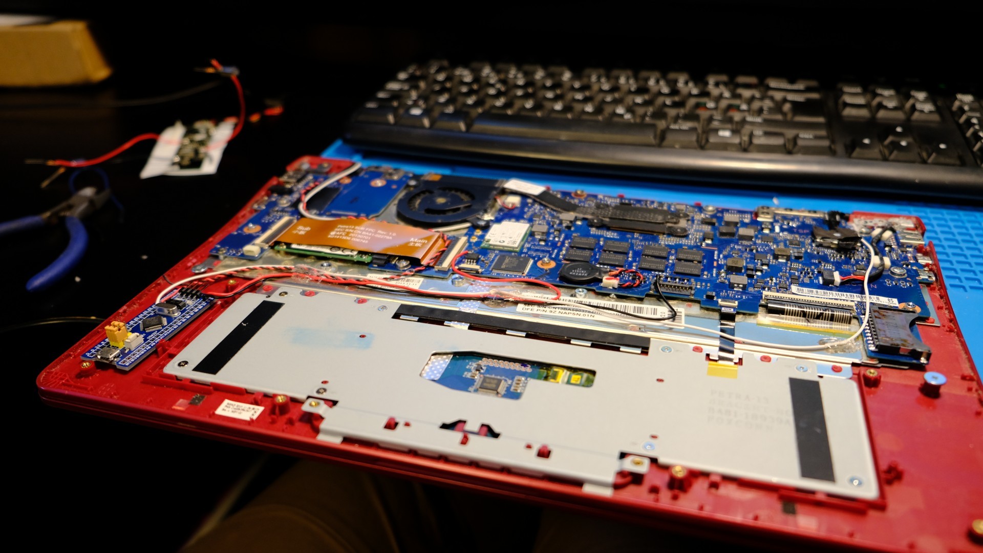
Open the laptop, and removing the battery |

Locate the power switch |

Solder wires to the pads of the switch |
Secure the wires with hot glue |
Locate the power LED |
Solder a wire to the pad that changes voltage |
Secure the wire with hot glue |
Found a good 3.3V power rail |
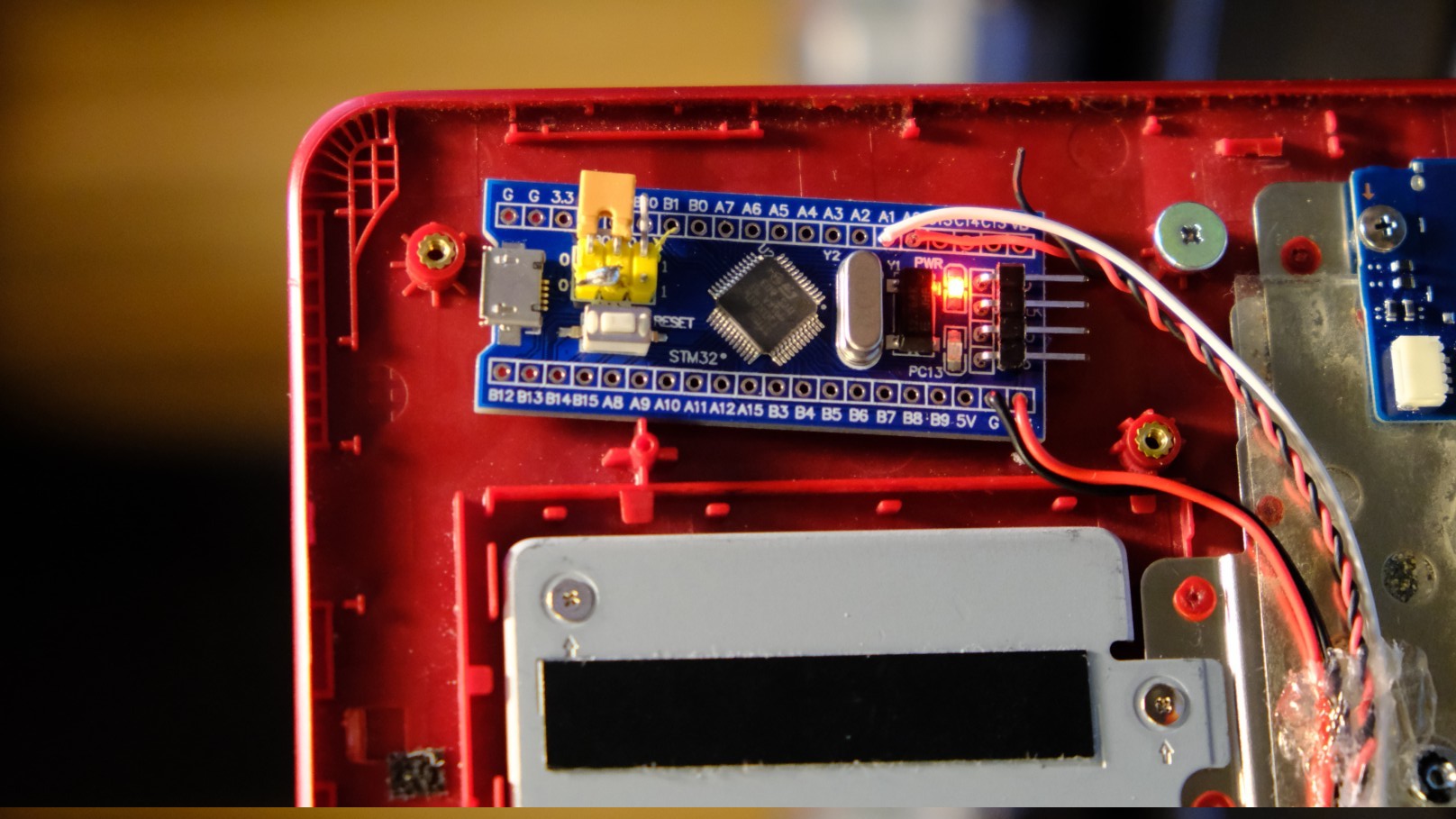
Solder all the wires to a microcontroler |
Cable manage the mess of wires |
A battery
Attention
Just don’t, seriously! Pick another device that would be as equivalent as possible but would not have batteries.
I see you are still reading, so I guess you are either a masochist or you really have no other choice so let’s just get to it, shall we?

Since we want our test machines to behave in the same way as users’, we should strive for minimizing the impact of our modifications to the machine.
When it comes to the internal battery, we ideally want it to be connected while the machine is running (mirroring how users would use the machine), and disconnected between test jobs so as to minimize the chances of any state leaking between jobs which would affect reproducibility of results.
We can achieve this goal at two levels: in software by hacking on the embedded controller, or physically by modifying the power-delivery.
1. Hack the Embedded Controller (EC)
If your device’s firmware or embedded controller (EC) is open source, you should be able to monitor the state of the power supply, and you probably can find a way to turn off the machine (the routine called when pressing the power button for 10s) when the main power supply is disconnected.
Unfortunately, the only devices with open source EC I am aware of are Chromebooks, so your only choice may be to…
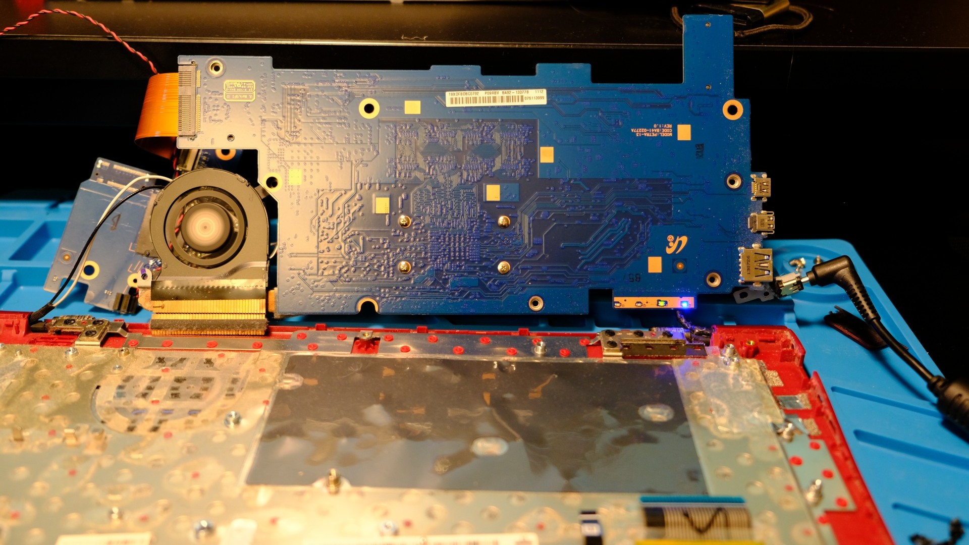
2. Instrument the machine’s power delivery
Danger
Do not mess with devices that operate with mains power without having experience! When at all possible, try to operate on logic boards operating at low DC voltages.
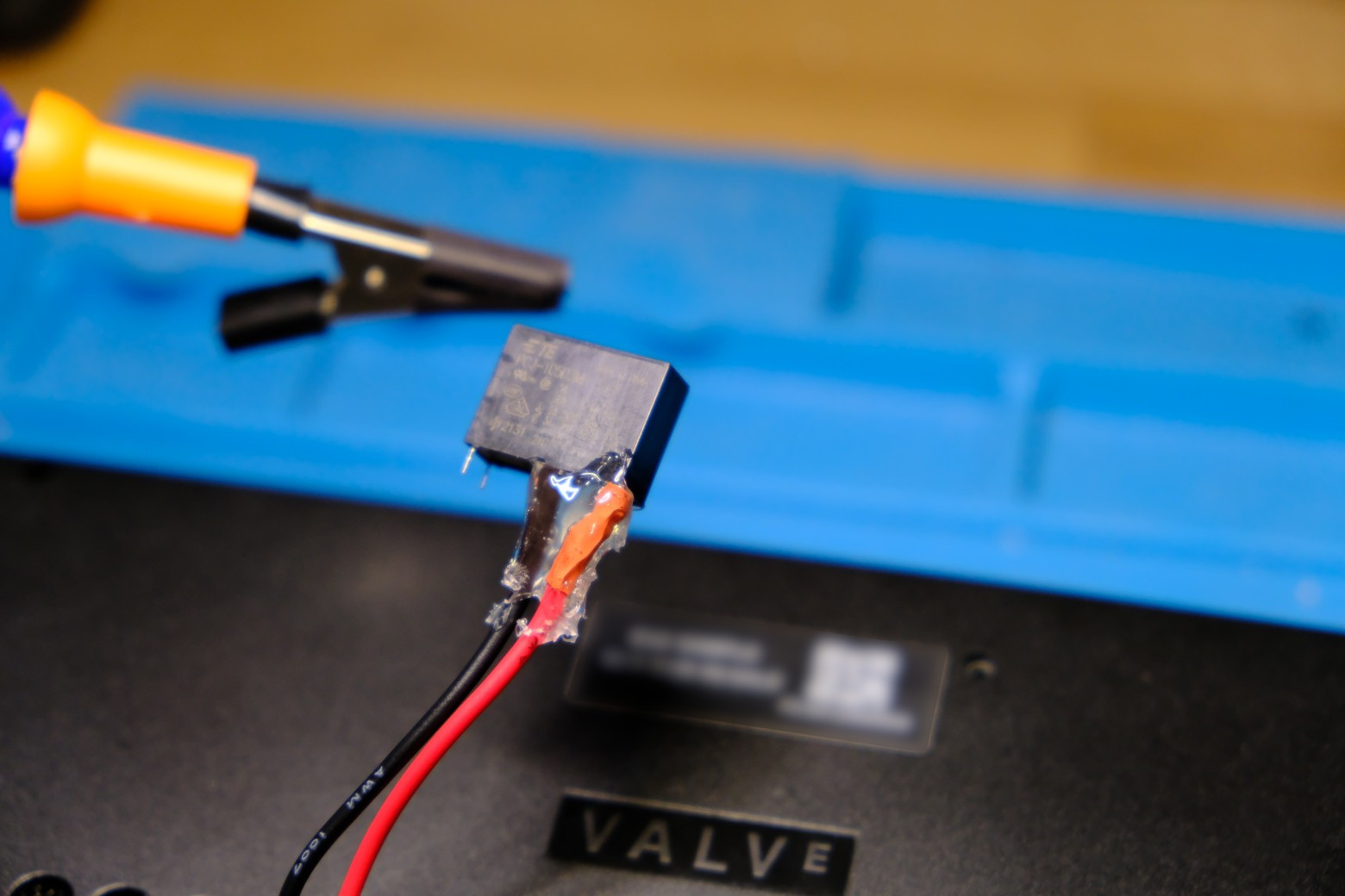
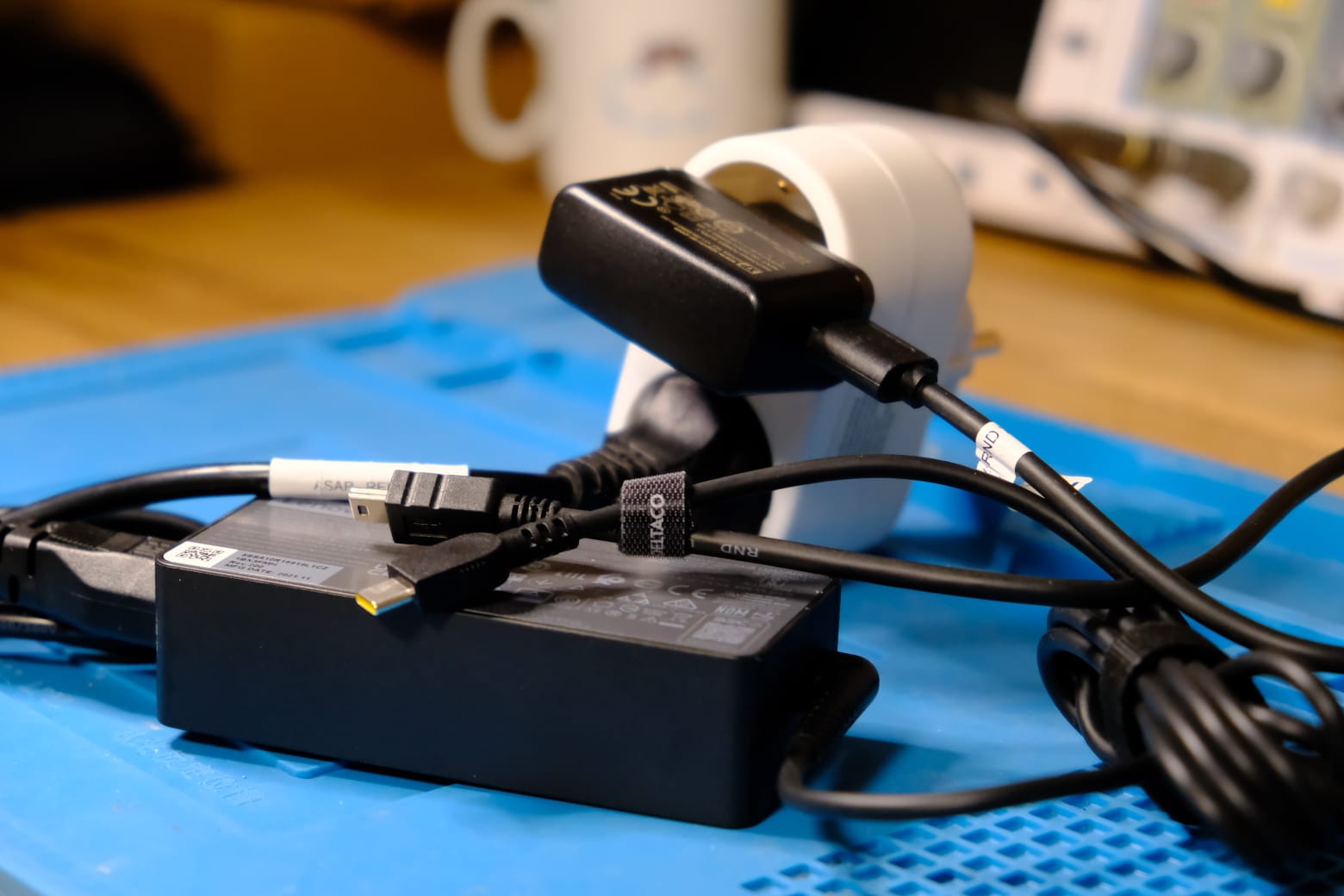
If we can’t get the embedded controller to do the work for us, we can do the same using a 5V relay with a normally-open contact, a few wires, a soldering iron, and an old USB power supply!
The first step is to figure out a way to detect whether the power supply is connected or not. The foolproof way is to use an old USB charger, connected to the same PDU port as the machine’s power supply. This will provide us with a 5V power supply when the machine is supposed to be ON, and 0V otherwise. We can then use this voltage to control a relay that will plug electrically connect the battery to the device’s motherboard.
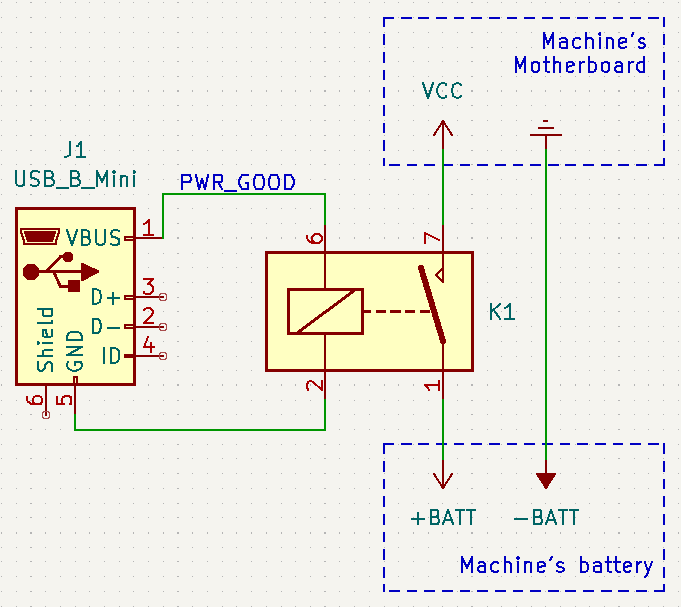
The rough schematic of how the battery plugging works
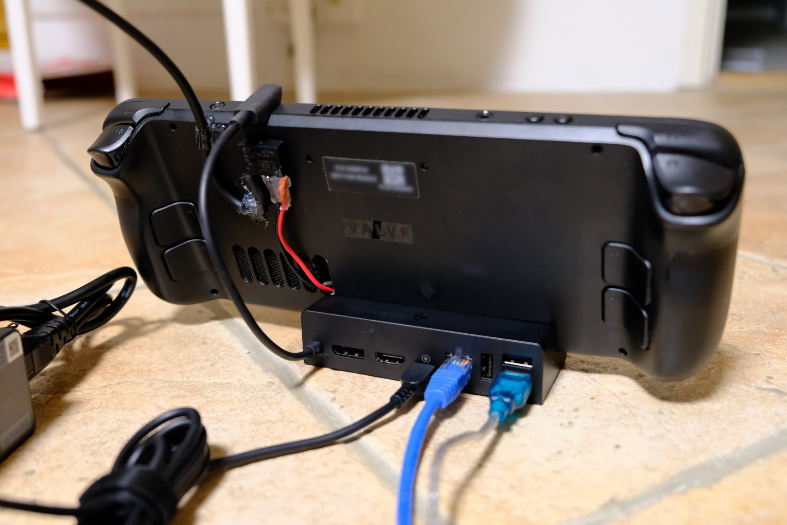
Disconnect the power to the machine
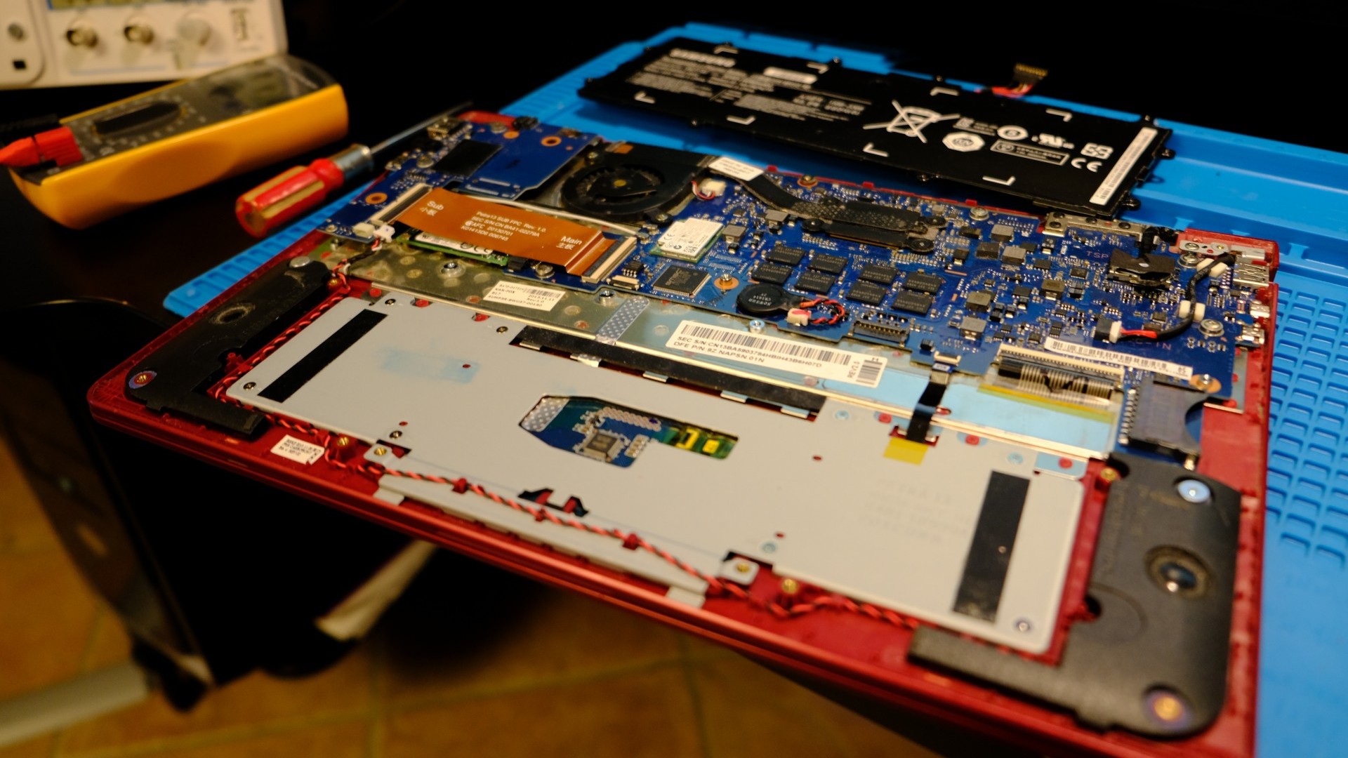
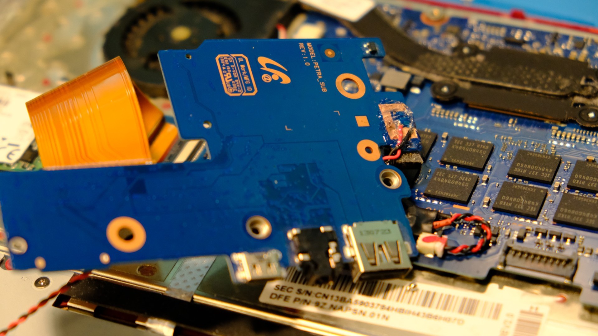
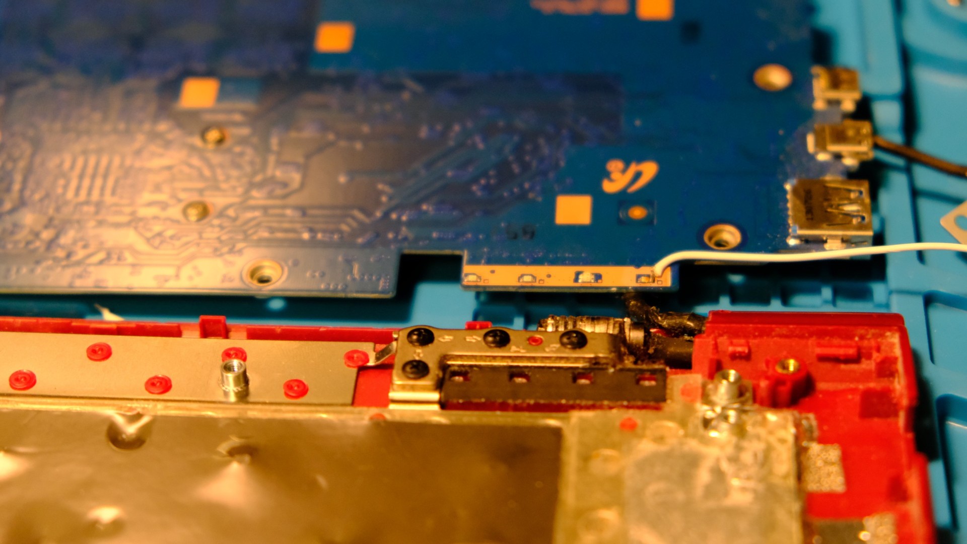
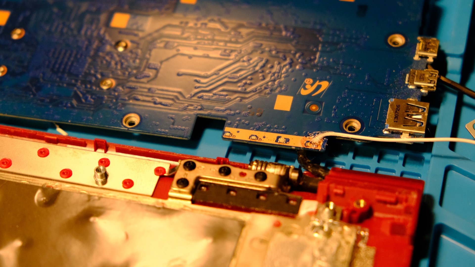
Open up the machine enough to access its main PCB and battery
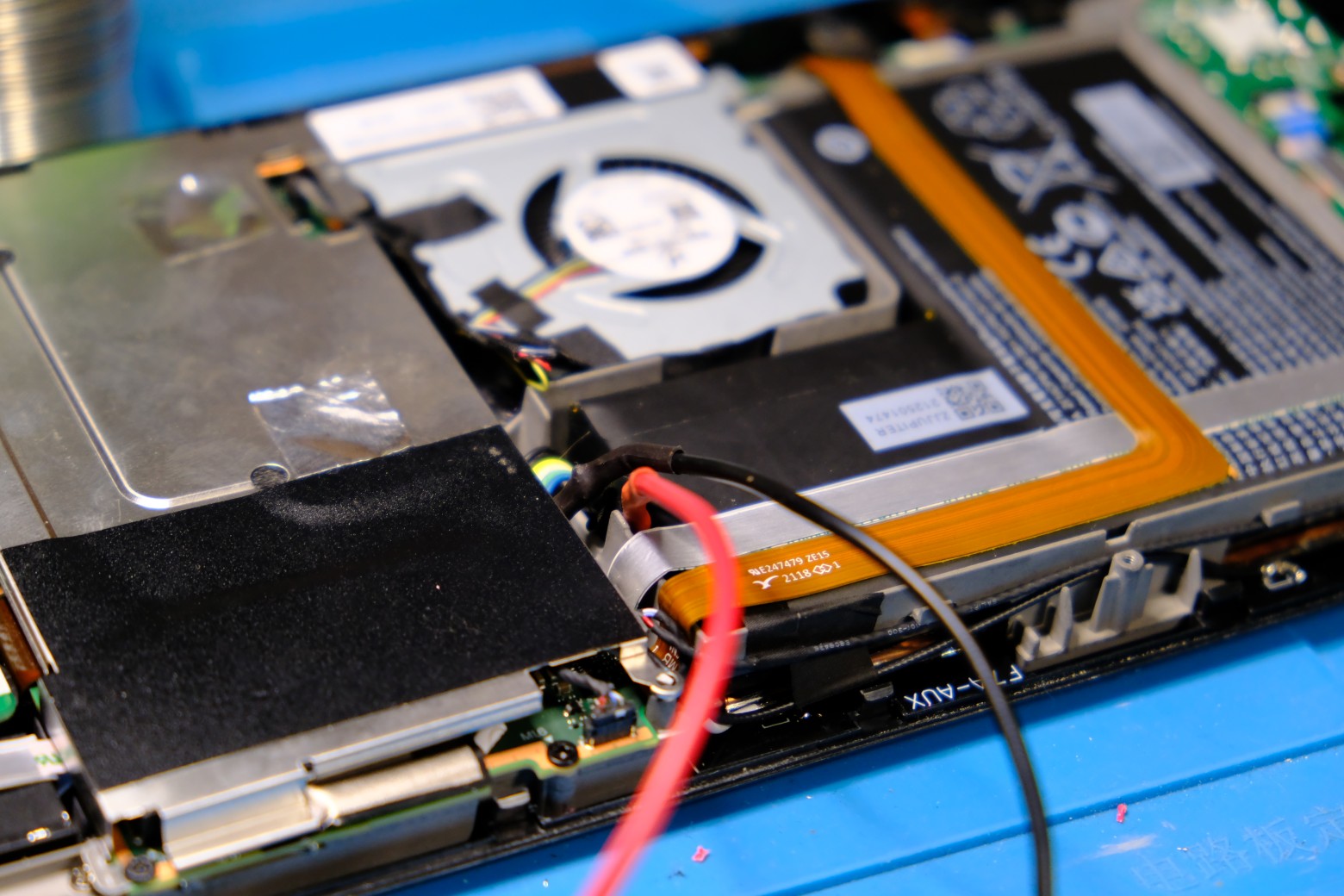
Disconnect the battery
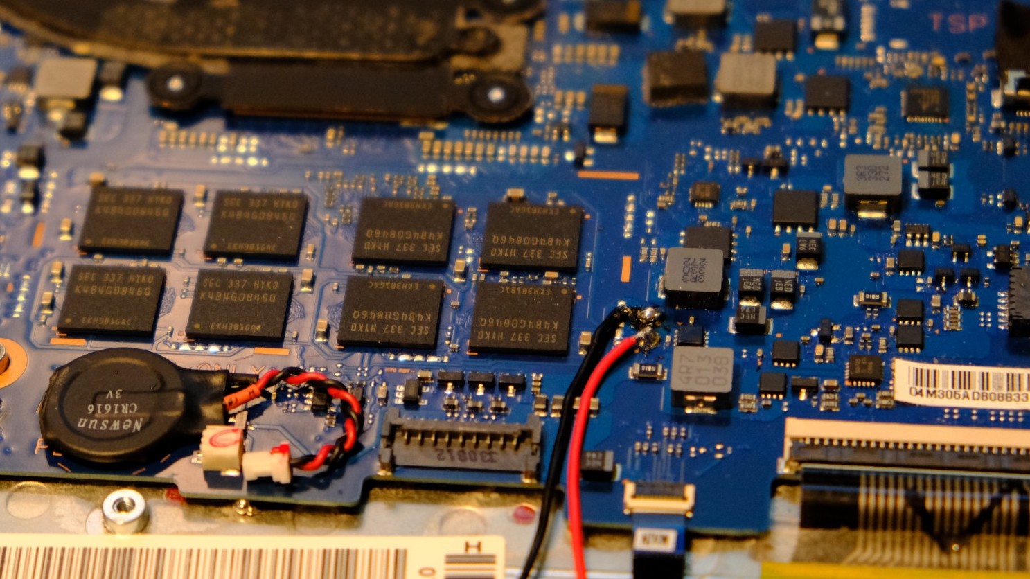
Identify the negative and positive leads of the battery using a voltmeter
Cut the positive lead(s)
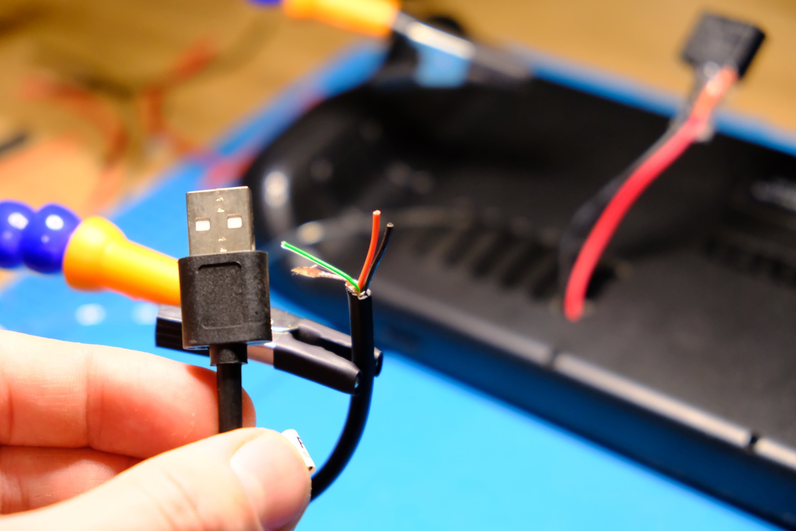
Solder extension wires to both sides
Solder them to the normally-open contacts of your 5V relay
Solder the coil leads of the relay to an old USB-A cable
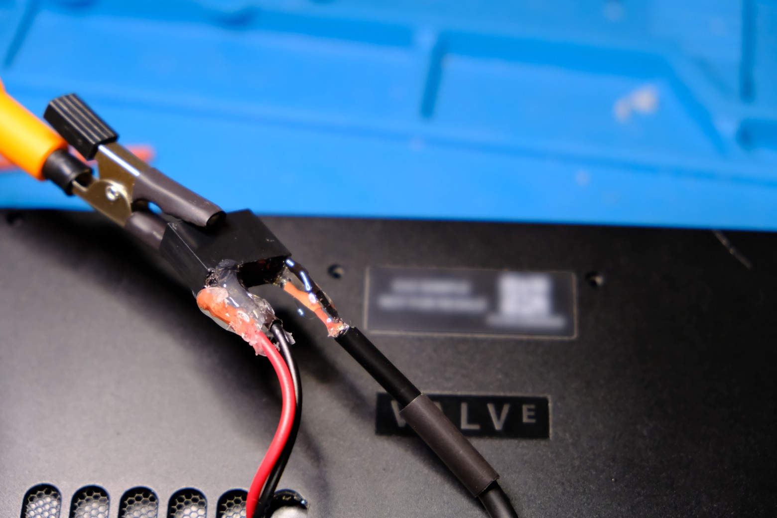
Secure everything with heatshrink and hotglue
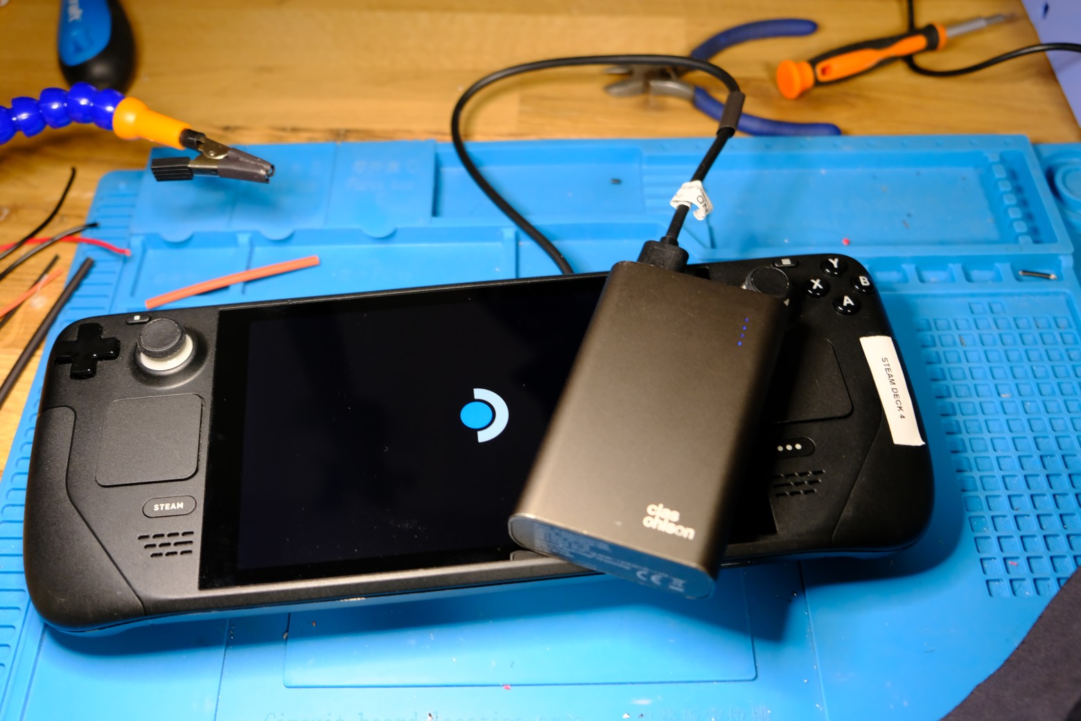
Close the machine and test it

|
|
|
|
|
|
|
|